Camera Simulator

Table layout · LTG fit · live Blender views

Casino floor / camera study
Preview mode Switch to the local view to control Blender and receive fresh renders.

Scene and live camera views

Use the overview to understand the full layout, then select a camera feed to edit it.

Key table components

296 BACC · original CAD parts · select a part to inspect

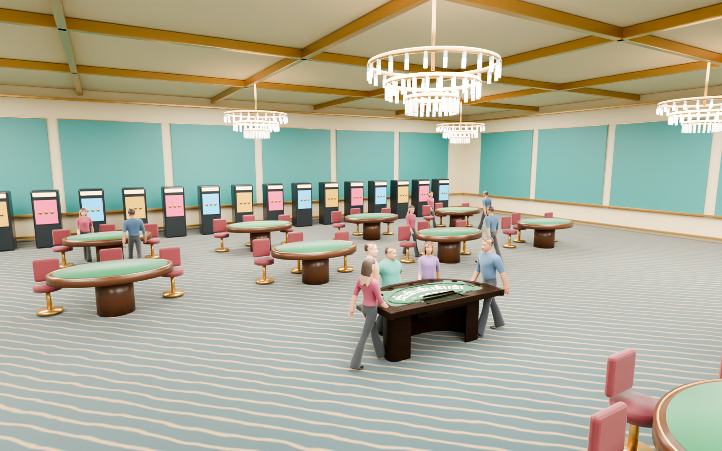
Casino floor 10,000 sq ft · 100 × 100 ft Blender-rendered casino interior with our study table, patterned carpet, bright walls and tiered chandeliers

Reference interior · enhanced original characters, not scanned people. The layout validator below retains its metric top view.

Layout validator
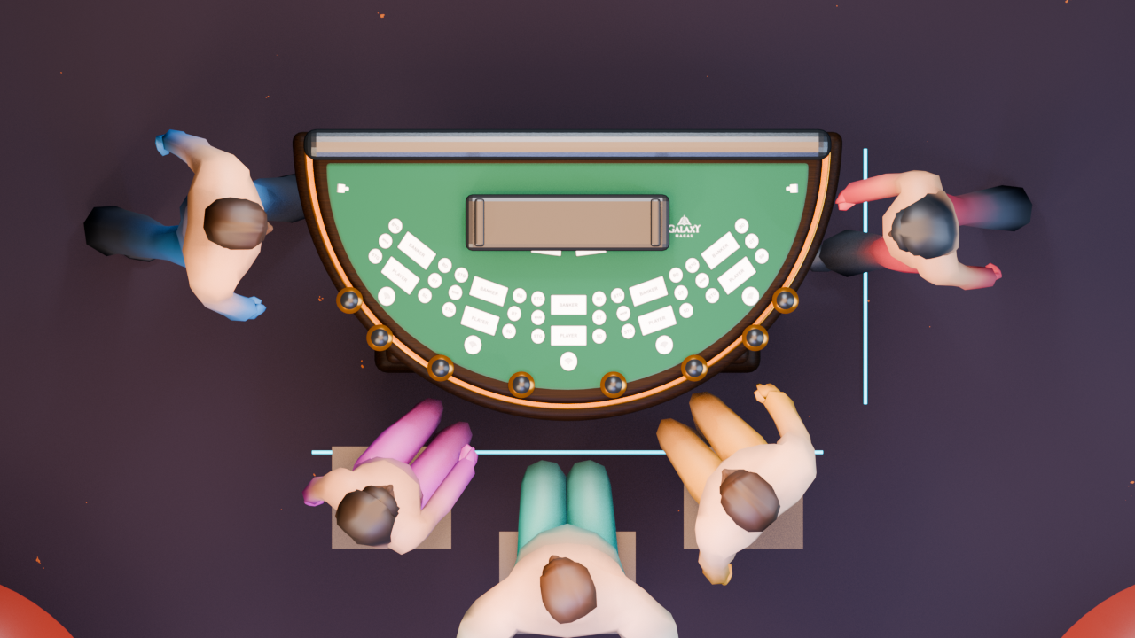
Top-down Blender render of the table, poles, cameras and players
OVERALL LAYOUT BIRD’S-EYE VIEW
TABLE CENTRE
Place the new camera Click where it should sit around the table The selected pole, camera and lens are added only at this new position
Camera colour keyDots = positions · fans = horizontal FOV · PTZ rectangles = ideal table-plane footprints, not occlusion checks

No cameras placed. Add a camera, or select LTG to add Diogo cameras at C1, C2 and C3.

✓ All views synchronizedBase scene loaded 0 feeds

Table components

Connect Blender to inspect the active setup.

Choose a component

Select a link on the left to inspect the actual Blender mesh.

Your camera positions and the table assembly stay unchanged.

Scene bounds · X × Y × Z
—
Centre · X / Y / Z
—

Dimensions describe the current scene, not manufacturing tolerances.

Open live Blender view ↗

Open in Blender launches a separate, isolated inspection copy for orbiting and measuring. It does not modify the live study.

LTG × DIOGO CAMERA

Does it fit? What can it see?

Loading the measured CAD reference…

Actual CAD pocket with the nominal Diogo camera head seated at its opening
Actual pocket CAD + nominal camera headThe head’s front datum is centred at the opening. Materials are illustrative; PCB and flex cable are omitted from this close-up.

Clearance, at the same scale

Camera size from the supplied drawing

The gap is true to scale, not exaggerated. Per-side clearance assumes the head is centred. Pocket manufacturing tolerance is unknown.

Head depth6.3 → 6.6 mmNominal → maximum
Head-envelope overlap—Available for closed-solid CAD only
Parts outside the pocket12.5 mm connector · 32 mm PCBRouting, mounting and retention not approved

What this check proves — and what it does not

The fit check tests nominal and maximum rectangular head envelopes against the supplied CAD at the pocket-opening datum. It does not confirm seating depth, retention, manufactured pocket tolerance, cable bends or board mounting.

Cycles traces light paths to produce the image. The coloured samples are separate, measured first-hit rays against Blender’s evaluated scene triangles. They use the same ideal H94° / 4:3 projection as the image (V approximately 77.6°). The drawing’s V76° and distortion limit are not a calibrated optical model. No internal lens refraction, lens distortion calibration or measured entrance-pupil offset is claimed.

A clear sampled ray is not proof that the entire image is unobstructed. Sampling counts are not percentages of blocked image area. Player hits and casino surfaces are scene content, not automatically fit failures.